OpenFlare: Rebuilding the V16 Warning Light with a Satellite Link
- Sascha Thiergart
- Company updates
- November 10, 2026
Embever and Antennity are developing OpenFlare for the European Space Agency (ESA): an open reference design for small non-terrestrial network (NTN) devices in the form of a V16 roadside warning light. Everything that can be made open will be published, from schematics to measurements. Here we explain what we are building, why, and what happens first.
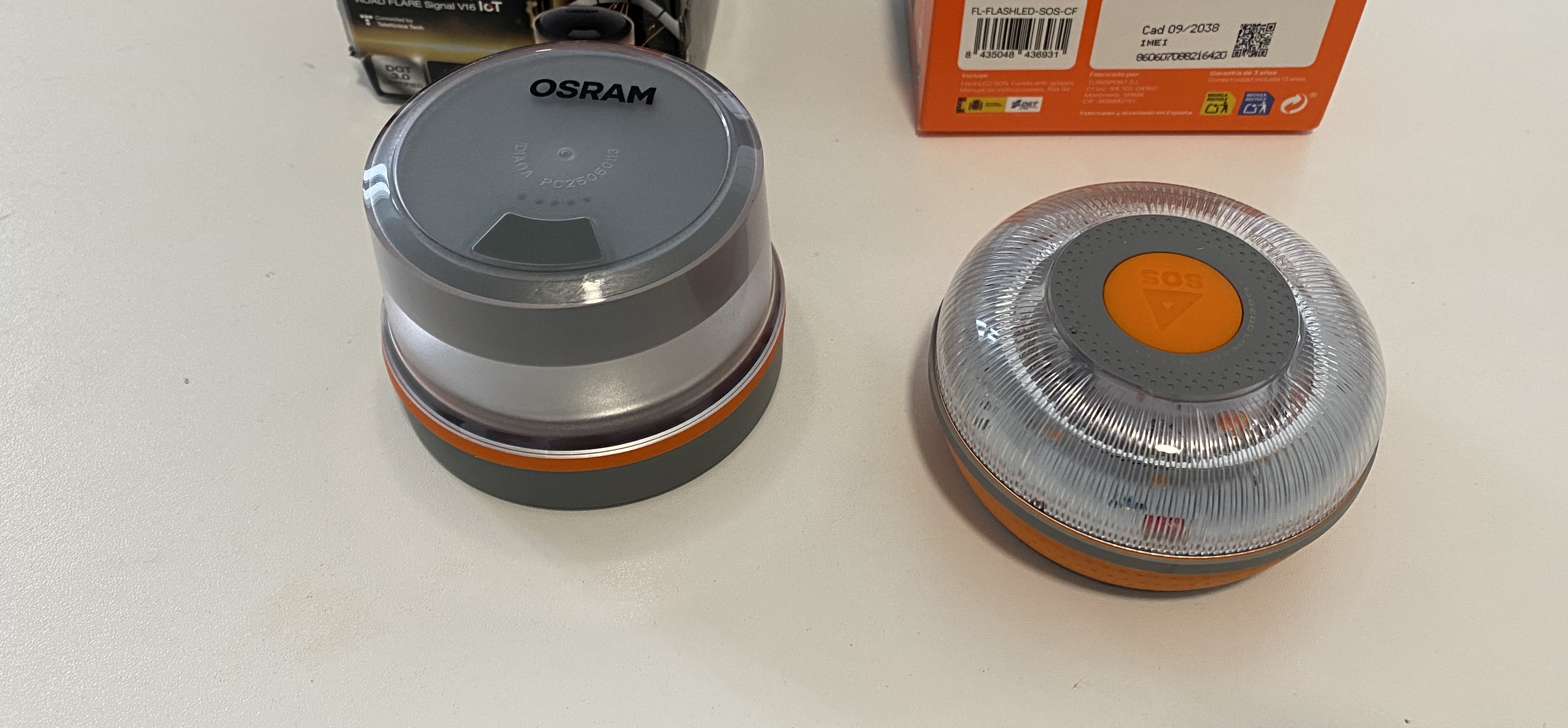
Two V16 warning lights from the market
A warning that depends on a network
Since 1 January 2026, connected warning lights have replaced the warning triangle in Spain. After a breakdown, the driver places the light, known as the V16, on the roof. It flashes and sends its position over the cellular network, so other road users are warned through a connected platform.
The numbers are large. According to Spain’s traffic authority DGT, about 30.5 million vehicles need one. If the rest of Europe followed, that would mean an estimated 250 to 270 million units.
The concept has one weak point: coverage. In a remote valley, a forest, or on a mountain road, the light still flashes, but the position never arrives. A breakdown in a place like that is exactly when the message matters.
What we are building
OpenFlare keeps cellular as the primary link and adds a satellite link as the fallback. The terrestrial connection is the energy-efficient default. The satellite takes over only where the network ends.
| Part | Our choice |
|---|---|
| Terrestrial link | LTE-M and NB-IoT |
| Satellite fallback | 5G NTN (NB-NTN) in the L-band |
| Positioning | GNSS L1 |
| Radio | Nordic Semiconductor nRF9151 |
| Antenna 1 | Notch antenna for GNSS L1 and L-band NTN |
| Antenna 2 | Dual-F antenna, mounted vertically on the side, for LTE-M and NB-IoT |
| PCB | Round, about 70 to 85 mm in diameter |
| Light | 360-degree warning light |
The antenna challenge
One of the main challenges is the antenna implementation. Terrestrial NB-IoT and LTE-M networks in Europe require support for band 20 (800 MHz). A disc of 70 to 85 mm offers little ground plane to work with at such low frequencies. For the satellite fallback, the antenna needs to support at least GNSS L1 and band n255 to work with Skylo. Since two antennas are coexisting on the board, a diplexer or RF switch will be needed to connect both antennas to the module.
First step: teardowns
We start with a screwdriver, not a schematic. We have ordered five V16 lights that are on the market today, and we will take each one apart and document it.
For every light we will record the same things:
- Radio chipset or module
- Antenna types and where they sit
- Battery and power design
- LED driver
- PCB layout and mechanical construction
The findings will be published here. After that, we continue with the light whose design suits our task best and replace its electronics with our own board. Its casing sets the limits for our PCB: the shape and size, the mounting holes, and the LED positions. The power supply will be designed around the existing battery.
Open by default
OpenFlare is a reference design, not a closed product. We will publish:
- System architecture and block diagrams
- Circuit diagrams and PCB designs
- Antenna implementation
- Firmware implementation
- RF and antenna measurements in the enclosure
Where something cannot be published, we will say so and say why.
More than a warning light
The warning light is the first application, not the only one. Take away the LED driver, add a sensor or a different power supply, and the same design becomes an asset tracker, an agriculture sensor, or an infrastructure monitor. Any battery-powered device that needs a position and a link from anywhere can start from OpenFlare.
Next post: what we found inside the V16 lights. Follow Embever on LinkedIn or check this blog to see each step as it happens. If you are developing a battery-powered device with cellular or satellite connectivity, get in touch at embever.com. We are glad to compare notes.


