Freetrack PCB Antennas
PCB antenna development kit
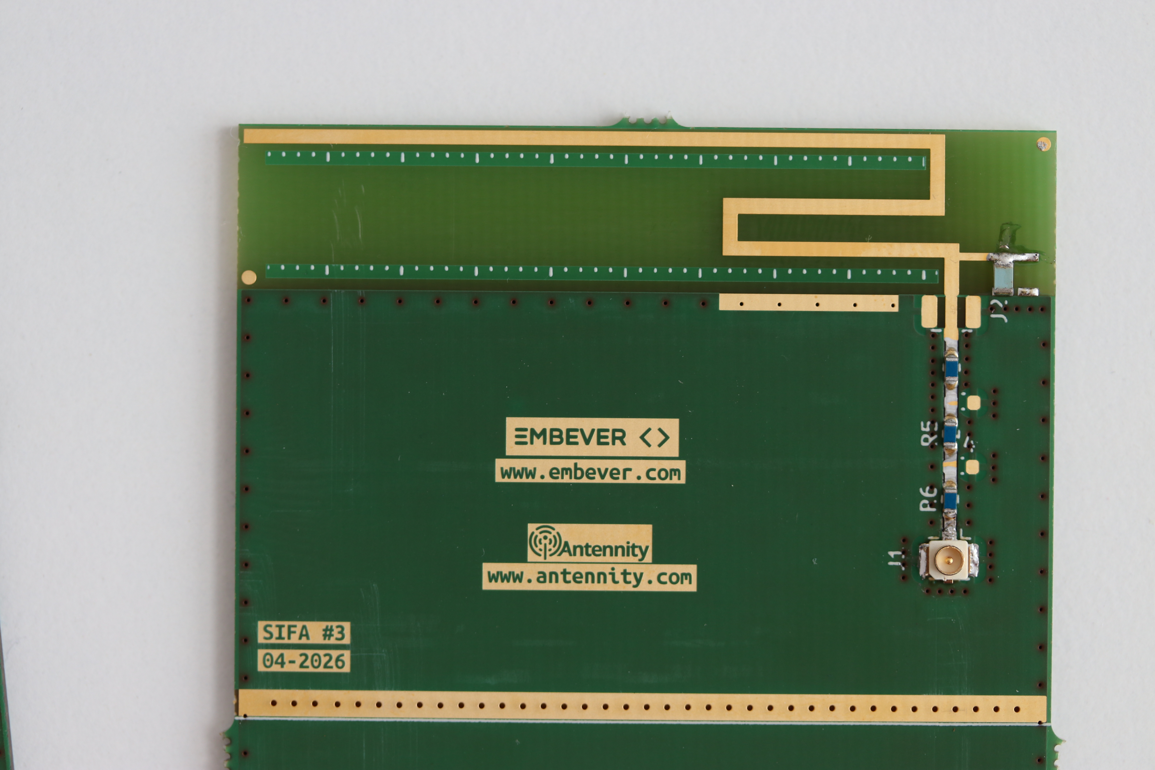
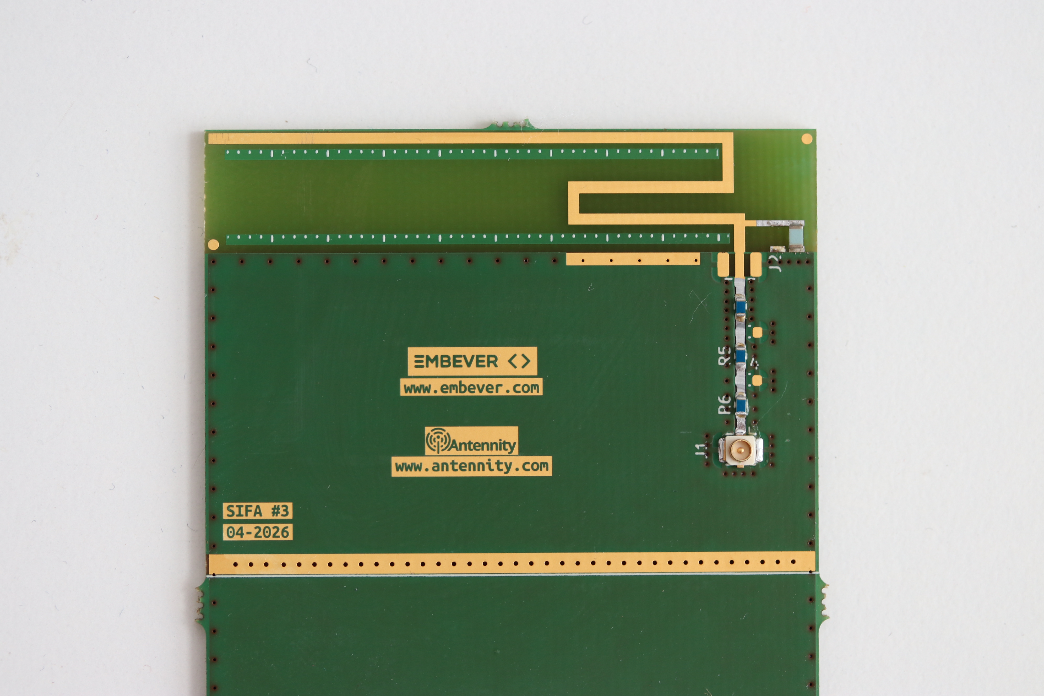
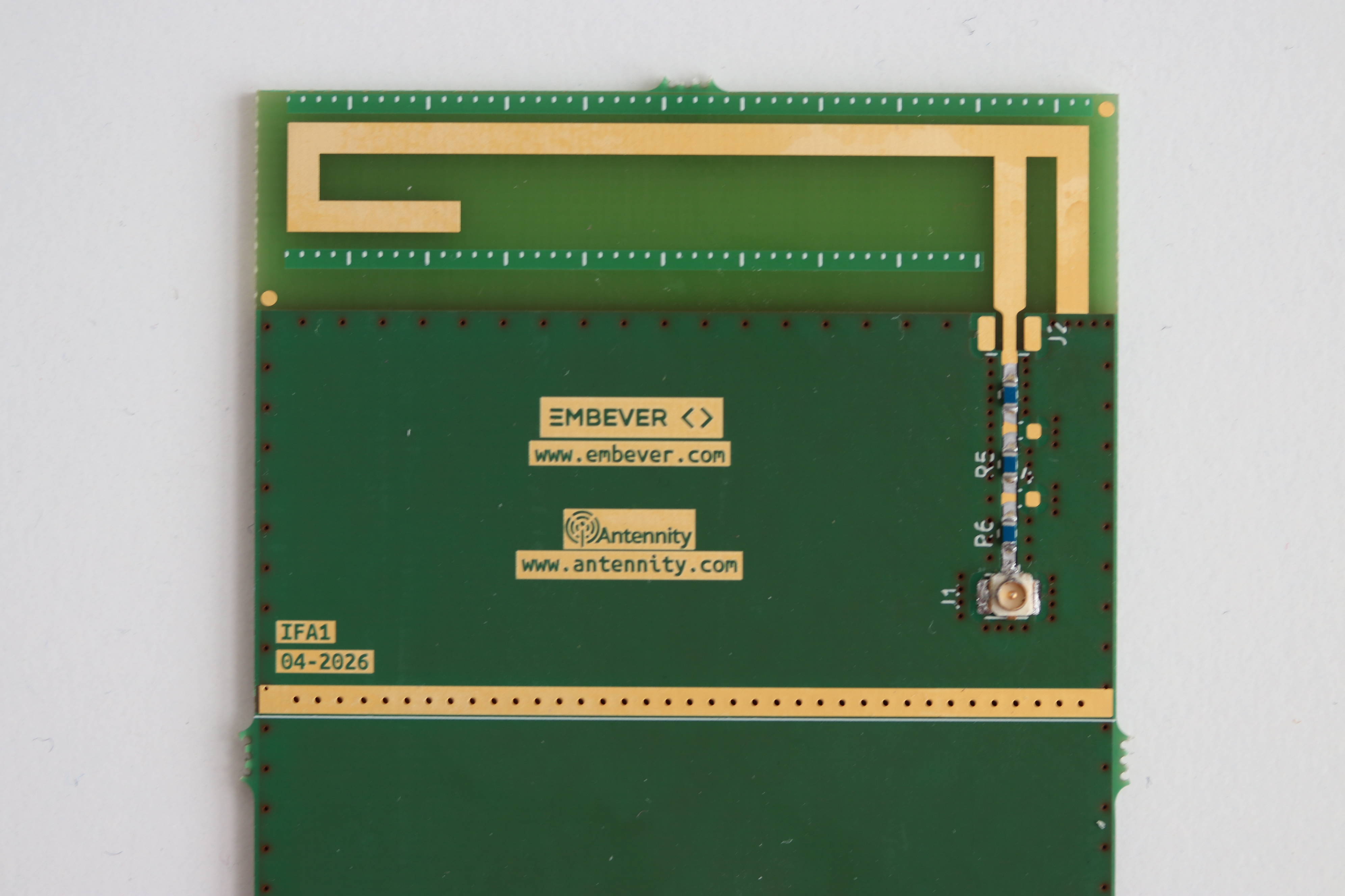
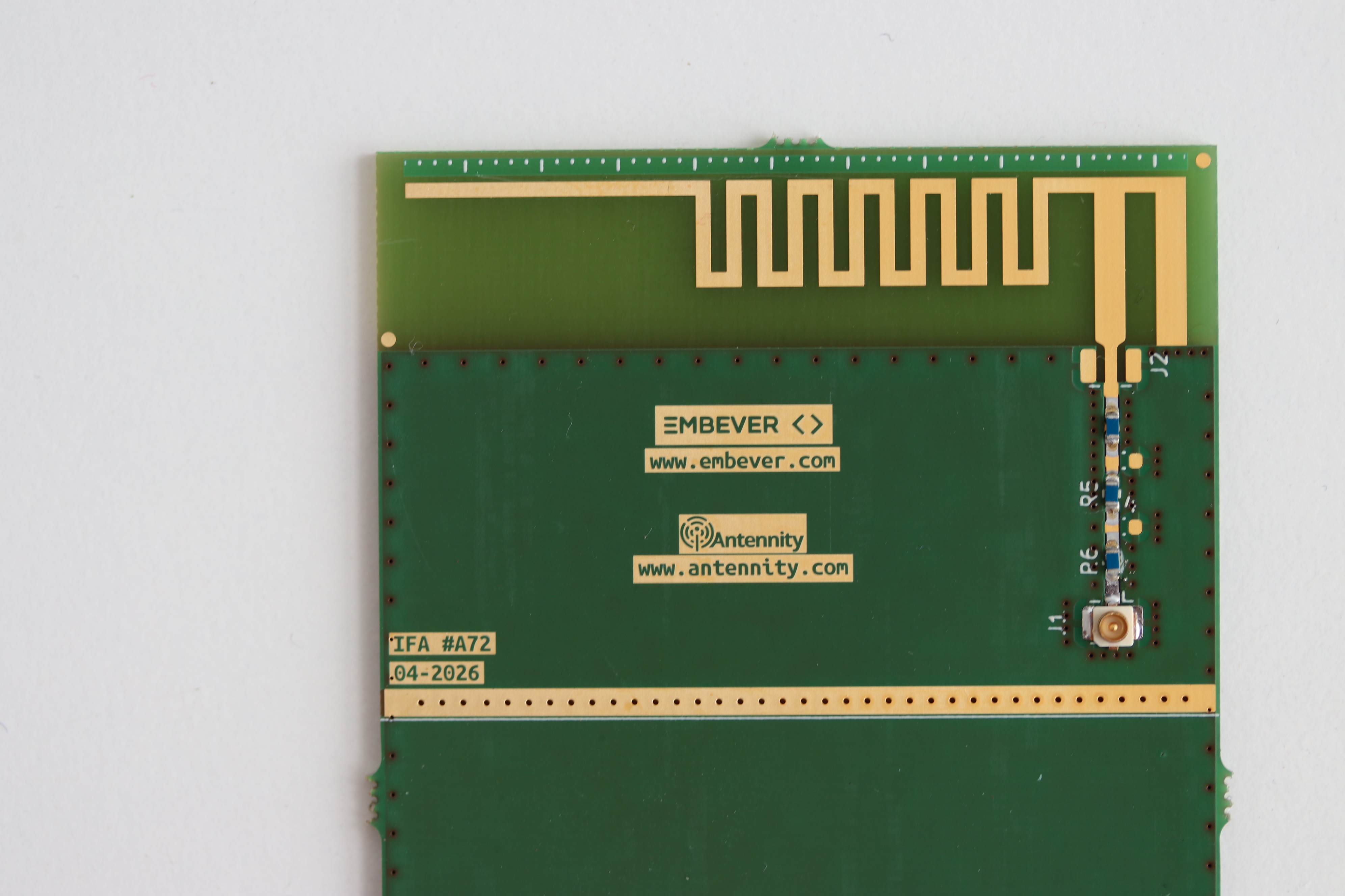
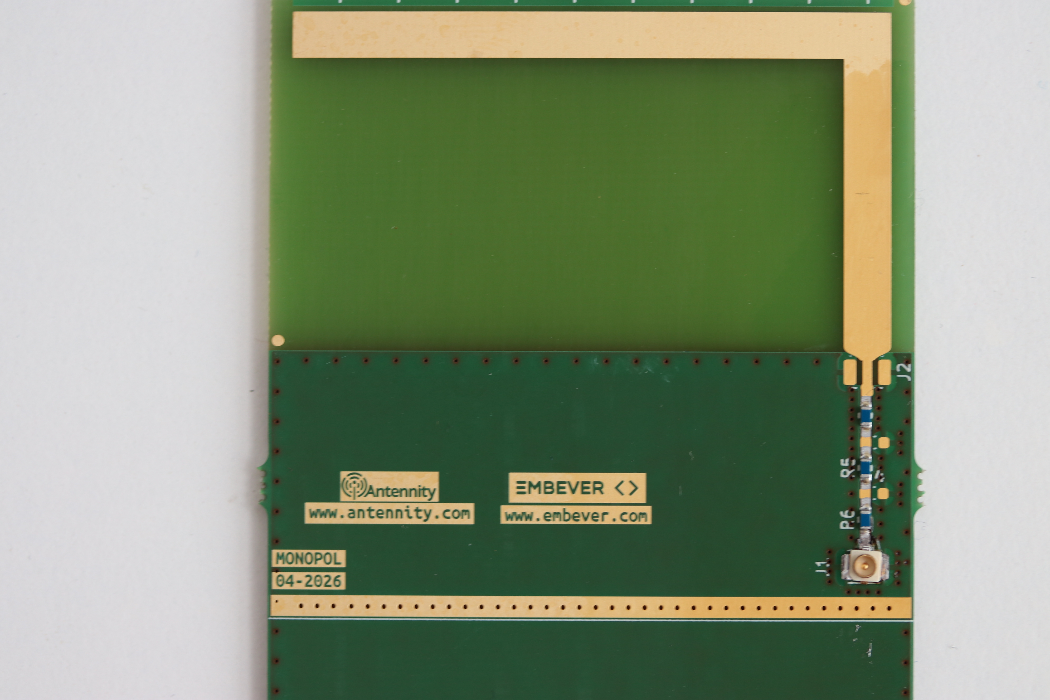
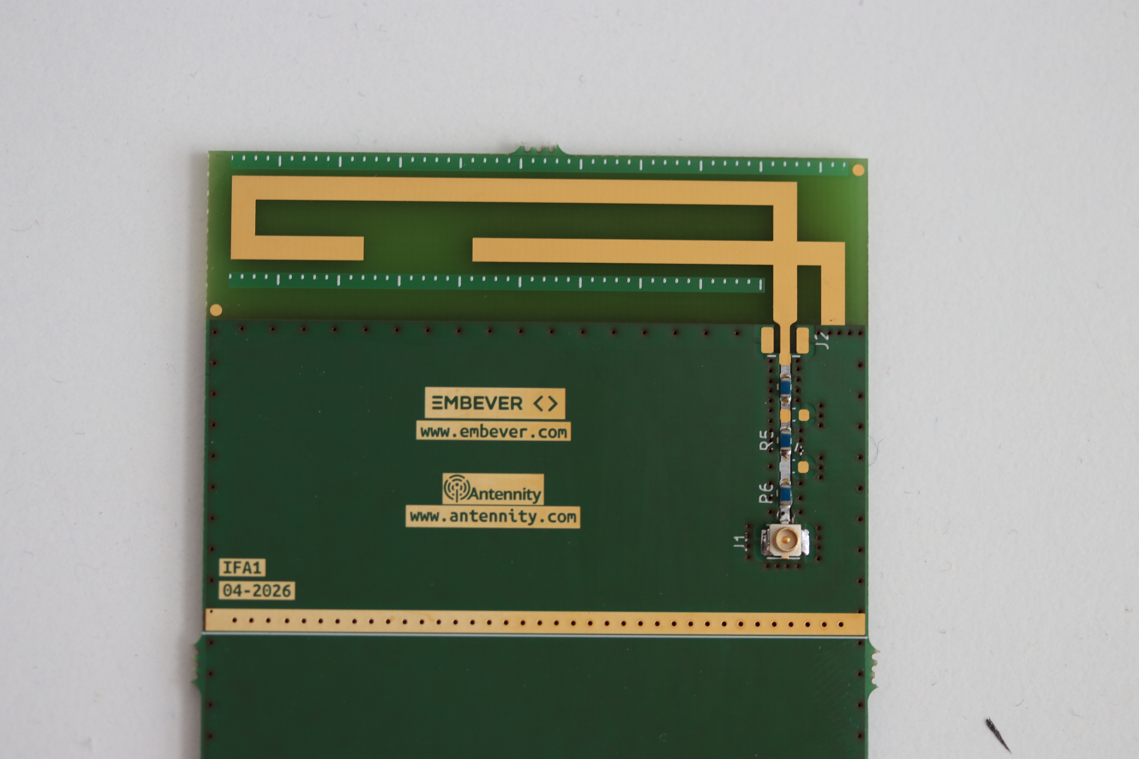
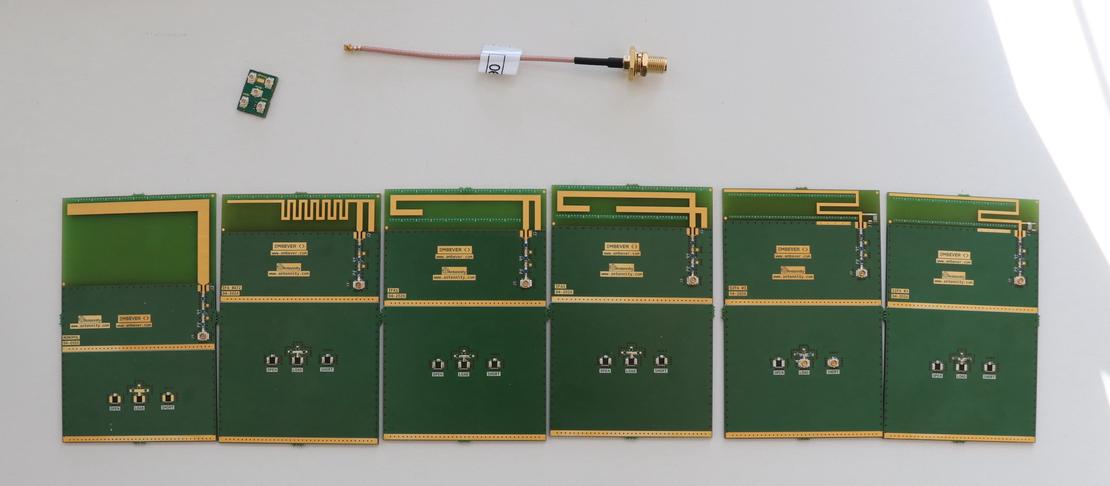
The FreeTrack Antenna Kit is an open hardware platform for evaluating and comparing planar antenna designs in the sub-GHz frequency range. It consists of five PCB antenna designs, each implementing a different radiating topology on a standardized 55×85 mm substrate. The kit is intended for RF engineers, researchers, and developers who need to characterize antenna performance, study the effect of ground plane size, or select the most suitable antenna topology for a given application. All five designs share a common board architecture: a U.FL feed connector, a five-component SMD matching network, a detachable calibration sub-board carrying OPEN, LOAD, and SHORT standards, and solder areas that allow the effective ground plane to be extended or reduced using copper foil. This makes it straightforward to measure each antenna under identical conditions and compare results directly.
Features
- Five different electrical antenna designs
- Monopol L-shape
- IFA (bent radiator)
- S-shaped IFA
- Meandered IFA
- Dual IFA
- 55×85 mm FR4 PCB substrate
- U.FL (IPEX) feed connector
- Five-component SMD matching network (L-, T-, or π-topology)
- Shiftable shorting pin via zero-ohm SMD resistor (IFA variants)
- Solder areas for copper foil ground plane extension or reduction
- Detachable calibration sub-board with OPEN, LOAD, and SHORT standards
- KiCad source files available for each design
- S1P files for unmatched antennas
Gallery